5/ February
Suction Filters: The Indispensable “Life Guardian” of Modern Hydraulic Systems
In the modern industrial body, built of steel, power, and precision control, hydraulic systems function like the “blood circulation system,” transmitting force and commands. Hydraulic oil is the lifeblood of this system. Yet, this blood is constantly threatened by contamination from “toxins” like dust, wear metals, and moisture. This is where the suction filter, silently installed at the pump’s suction inlet, plays the critical dual role of the system’s “kidney” and “first line of immune defense.” Its mission extends far beyond simple filtration; it is to ensure the health, longevity, and efficient operation of the entire hydraulic organism through source containment, proactive warning, and system protection.
I. Core Duties: Source Protection Beyond Filtration
The value of a suction filter is built upon a fundamental vulnerability of hydraulic systems: the hydraulic pump—the “heart” of the system—is extremely sensitive to contaminants. Micron-sized hard particles are enough to score its precision surfaces, accelerate wear, and cause internal leakage, efficiency loss, or even catastrophic failure.
Thus, the core duties of a suction filter are layered as follows:
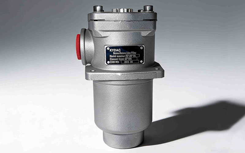
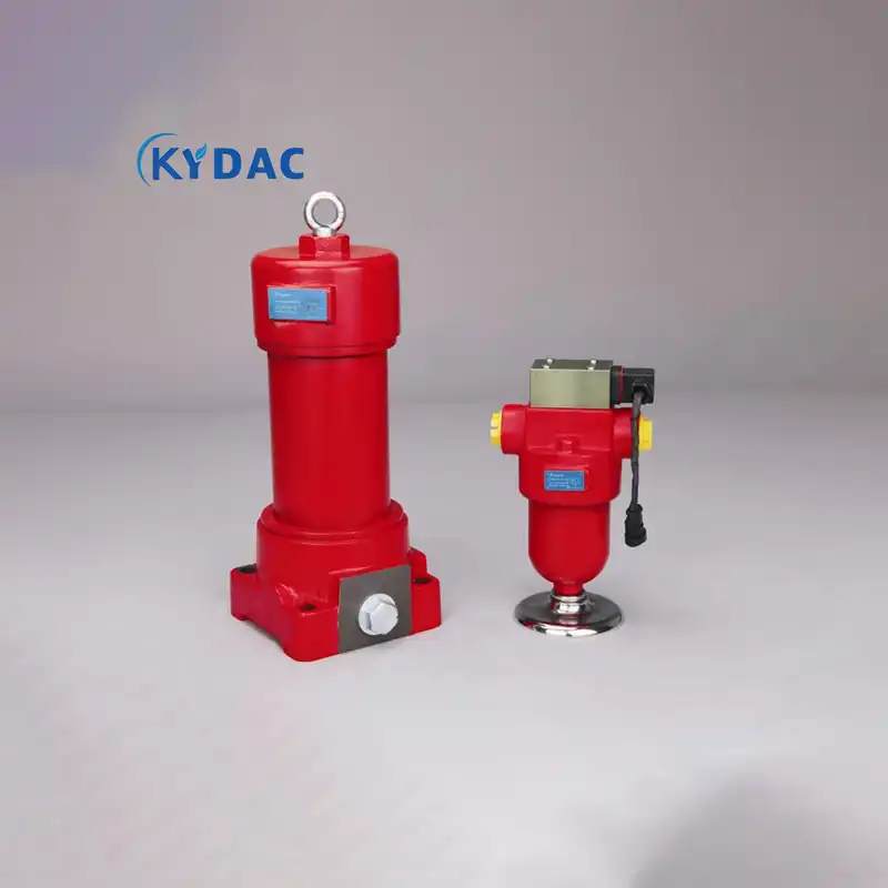
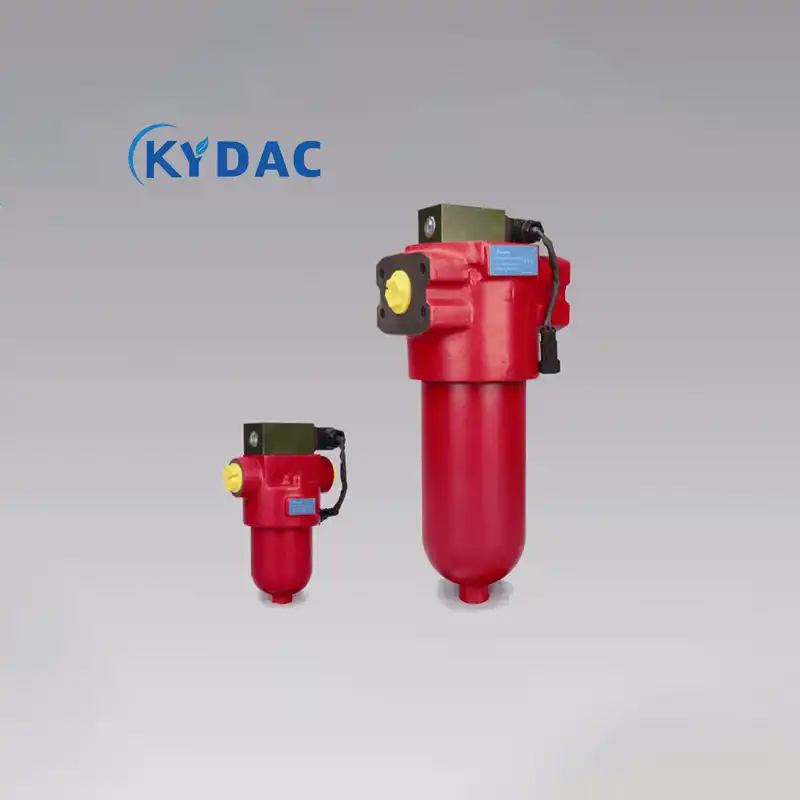
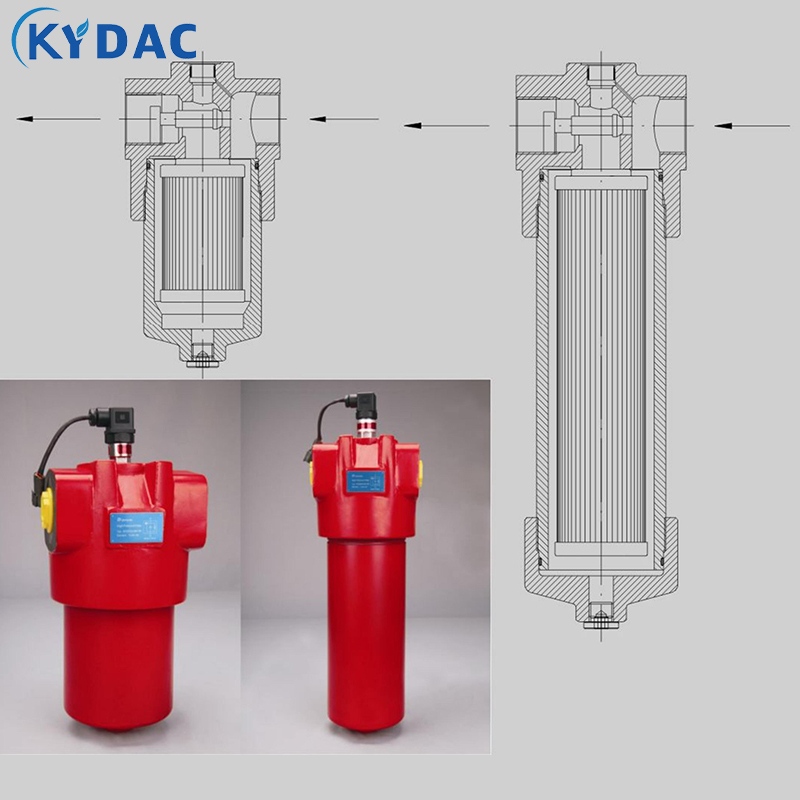
Absolute Interception: Physically trapping contaminants via the filter element (often wire mesh or synthetic fiber) before they enter the hydraulic pump. The chosen filtration rating (e.g., 100µm, 40µm, 10µm) directly defines the starting point of cleanliness for all downstream components.
Stable Oil Supply: It must be designed for low flow resistance to ensure the pump does not suffer from oil starvation or cavitation during cold starts or with high-viscosity fluid, which can damage the pump.
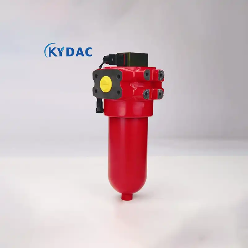
Safety Assurance: Equipped with intelligent accessories (like clogging indicators and bypass valves), it alerts when the element is loaded and provides an emergency flow path in extreme conditions. Its highest principle is “protecting system continuity takes priority over temporary filtration accuracy.”
II. Technological Evolution: From Passive Component to Intelligent Node
The modern suction filter has evolved beyond a simple filter housing, integrating multiple active protection and user-friendly features:
Clogging Indicator: Activates (via electrical contact or visual gauge) when the pressure differential across the element reaches a set value (e.g., 0.018 MPa), signaling the need for service. This enables a shift from “time-based replacement” to “condition-based maintenance,” facilitating predictive upkeep.
Bypass Valve Protection: If the pressure differential rises further to a critical threshold (e.g., 0.02 MPa), the bypass valve opens automatically, allowing unfiltered oil to pass through. This seemingly “compromising” design actually prioritizes global system safety—preventing pump dry-running and system shutdown—over temporary local cleanliness, embodying a deep system-protection logic.
Anti-Drain Valve Design: During element change-out, a built-in anti-drain valve automatically seals the tank port, enabling leak-free, non-draining quick maintenance. This significantly reduces fluid waste, environmental contamination, and improves service efficiency.
III. Industry Applications: Customized Protection for Demanding Conditions
Different industrial sectors pose varied performance demands on suction filters:
Industry Sector
Core Challenge
Suction Filter Solution Focus
Construction & Agricultural Machinery
Constant vibration, shock, dusty outdoor environments
Robust construction, anti-vibration design, high dirt-holding capacity, coarse filtration (100-150µm) with metal guard screens to ensure reliability in harsh conditions.
Machine Tools & Injection Molding
Precise systems, high oil temperature, need for long-term stability
Medium to high filtration ratings (25-40µm), good compatibility, mandatory use of indicators and bypass valves to ensure process stability.
Marine & Offshore Engineering
High humidity, salt spray corrosion, space constraints
Full stainless steel construction, excellent corrosion resistance, compact design to meet stringent marine environmental and safety standards.
Power Generation & Metallurgy
Large-scale systems, high oil temperature, extremely high downtime costs
High-flow, high-strength design, superior dirt-holding capacity and long-term stability, support for on-line element change-out to enable maintenance without shutdown.
IV. Value Elevation: The Cornerstone of Cost Control & Reliability Engineering
The economic value of a suction filter far exceeds its purchase price:
Cost Amplifier Effect: ¥1 of contamination damage can lead to hundreds or thousands of yuan in pump/valve damage, and tens of thousands in production downtime losses. The suction filter is the most cost-effective preventive investment.
Foundation for System Longevity: Clean fluid is the cornerstone of long hydraulic component life. Effective source filtration can extend the service life of critical system components by multiples, dramatically reducing lifecycle maintenance and replacement costs.
Guardian of Energy Efficiency: Maintaining system cleanliness reduces internal leakage caused by wear, keeping the hydraulic system operating in its efficient range and saving energy consumption.
Conclusion: Profound Impact from the Unseen
The suction filter, typically hidden inside or on the side of the reservoir and unseen by most, defines the health baseline of the entire hydraulic system through its silent, steadfast operation. It is not merely a physical barrier but an active protection system integrating the principles of fluid dynamics, materials science, and safety engineering.
In today’s industrial landscape, where equipment demands higher reliability, lower total cost of ownership, and smarter maintenance, selecting a suction filter that matches the operating conditions and offers reliable performance is crucial. It represents a thoughtful safeguard for core assets and a solemn commitment to production continuity. Unseen, it protects the purity and power of modern industry’s lifeblood.
Learn More